EcoCONNECT technical notes
Structure and specifications
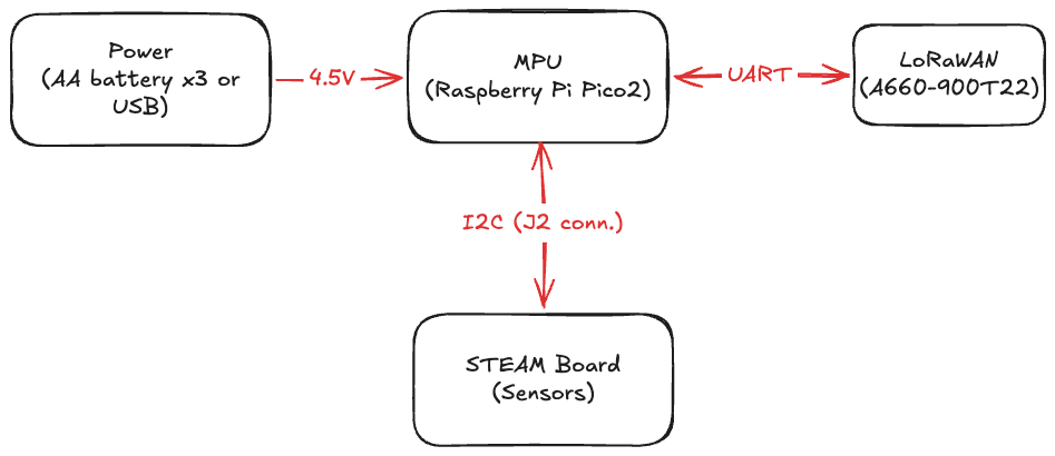
EcoCONNECT is made of a main board and a STEAM board. It runs on three alkaline batteries or USB power, and it is an IoT device with several connector wires you can use freely.
Specifications
| Item | Value |
|---|---|
| MPU | Raspberry Pi Pico 2 |
| Data communication | LoRaWAN (A660-900T22) |
| Development language | MicroPython |
| Sensors | Temperature / humidity / pressure (BME280), illuminance (BH1750) |
| Power | Three alkaline batteries |
Main board
Overview
The main board processes data from each sensor device and sends that data. It is a four-layer board. The MPU is a Raspberry Pi Pico 2, connected to the LoRaWAN module (A660-900T22) by serial communication. It also talks to the sensors on the STEAM board over an I2C bus.
The LoRaWAN module (A660-900T22) can be fitted either as the module alone or as the evaluation module. To check LoRaWAN behavior, mount the evaluation module on pin headers. Debugging is smoother that way.
Pin assignment
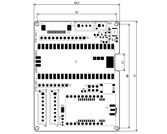
Role and pin assignment of each connector. When you use the STEAM board, connectors J1 and J2 are used. Pins on the expansion connectors (J4 and J6) are free to use. The firmware-update connector (J7) is used when updating the LoRaWAN module firmware. Pins on the add-on board connectors (J5 and J8) are reserved for future expansion.
| Connector | Pin assignment | Use |
|---|---|---|
| J1 | 1 : GND 2 : VBAT sens. 3 : VBAT 4 : Reserve | Connect to the battery |
| J2 | 1 : SCL 3 : SDA 5 : 3V3 2/4/6/7/8 : GND | Connect to the STEAM board |
| J4 | 1 : VBUS 2 : 3V3_EN 3 : 3V3 4 : ADC_VREF 5 : AGND 6 : GPIO19 7 : GPIO18 8 : GPIO17 | Expansion connector (connected to Raspberry Pi Pico pins) |
| J5/J8 | 1 : GPIO16 4 : VSYS 6 : J8 P4 7 : J8 P5 10 : J8 P1 2/3/5/8/9/11/12 : GND | For a planned add-on board |
| J6 | 1 : GPIO2 2 : GPIO4 3 : GPIO5 4 : GPIO6 5 : GPIO7 6 : GPIO8 7 : GPIO9 8 : GPIO10 9 : GPIO11 10 : GPIO12 11 : GPIO13 12 : GPIO15 | Expansion connector (connected to Raspberry Pi Pico pins) |
| J7 | 1 : VCC 2 : CTS 3 : SETB 4 : GND 5 : TXG 6 : XRES | Firmware update (A660-900T) |
Physical layout and connector positions
STEAM board
Overview
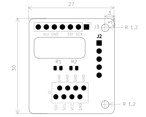
This is a four-layer board with environmental sensors (temperature, humidity, ambient light, and pressure). Each sensor talks to the MPU on one I2C bus.
The sensors expected on the board are the BME280 (temperature, humidity, and pressure) and the BH1750 (illuminance). Mount the BME280 on the front of the board and the BH1750 on the back.
Add pull-up resistors (R1 and R2) when the sensor module you use does not already include them.
Pin assignment
| Connector | Pin assignment | Use |
|---|---|---|
| J1 | 1 : SDA 3 : SCL 5 : 3V3 2/4/6/7/8 : GND | Connect to the main board |
| J2 | 1 : ADDR 2 : SDA 3 : SCL 4 : GND 5 : 3V3 | Connect to the BH1750 (back of the board) |
| J3 | 1 : SDO 2 : SCL 3 : SDA 4 : CSR 5 : GND 6 : Vcore 7 : VIO | Connect to the BME280 (front of the board) |
Physical layout and connector positions